The Fiero Project

776982490

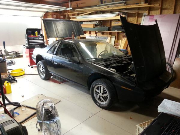
Some years ago my grandfather gave me an old Pontiac Fiero that had been sitting dormant for nearly twenty years. No precautions were taken to store or preserve it; it just sat outside in the elements with an undiagnosed engine problem keeping it from being moved. Once it was towed to my parents place, it sat in a garage for some years as I wondered where to begin with such a project. There where many obvious problems, and a lot needing fixing, from weathered and faded paint,and a broken windshield, to ancient gasoline in the tank, and the unknown engine problem. As I neared the end of earning a bachelors degree in Mechanical Engineering, I began to take the project much more seriously. Last summer I jumped right in and started by cleaning out the fuel system.

Starting with the basics, I turned over the engine by hand to make sure nothing was seized up. Next, I changed the fuel filter, as well as the oil and battery, which predictably did almost nothing; the engine turned over just fine but wouldn’t start. So, I jacked the whole car up and dropped the gas tank; which, by the way, was atrocious on the inside. After disposing of what was surely no longer gasoline, I hosed it out with a gallon of industrial degreaser . Followed by a good soaking with muriatic acid. I also tried using phosphoric acid, since the tank flash rusted shortly after the first cleaning. In my opinion it’s not really worth the fuss, the tank still flash rusted, and I don’t really like playing with strong chemicals. Now that it was clean I painted it and replaced the fuel pump ,and assorted rubber parts that had turned to goo.

779226120 784899883

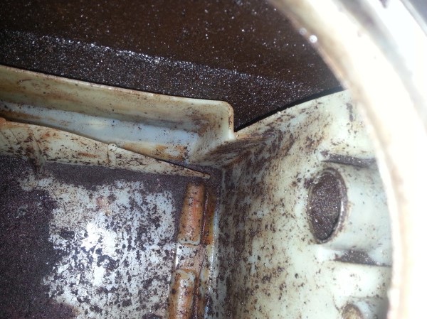
Before and after pictures of the inside of the gas tank.


781134409 781134795

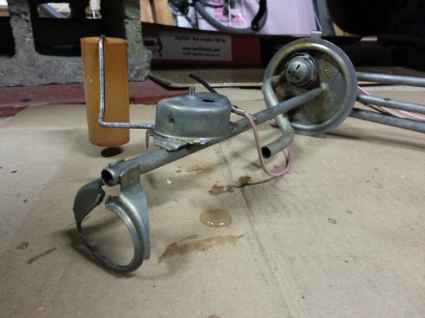
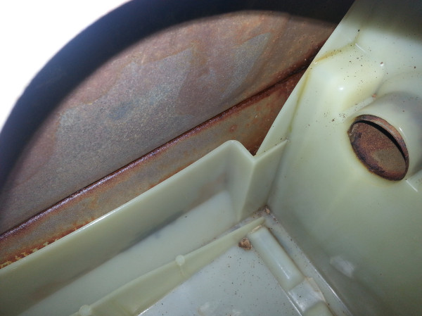
Before and after pictures of the fuel sender.


788404985

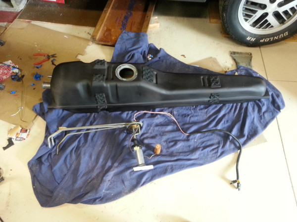
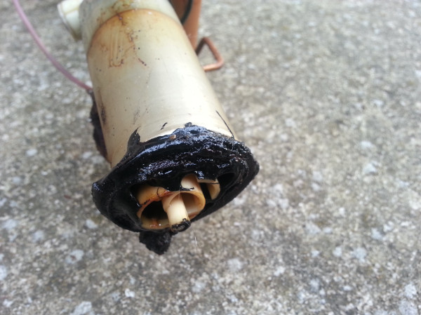
The finished fuel tank and fuel sender.


Now surely, I though, I should get something out of the engine; and I did. What I got was what sounded like an extremely rough idle before eventually stalling. Now I was getting somewhere. Following the advice of a friend I picked up a cheap compression tester, and tested the cylinders one by one. The fourth cylinder I tested had no compression. Next step: Engine Surgery. I popped off the valve cover, and voila! A jammed valve and a snapped pushrod. From what I can gather it seems an excess amount of carbon propped the valve in an open position. Then, with no force acting on the rocker arm to keep the pushrod seated it moved out of place, the rod jammed against it, buckled, and snapped in two.

792460111 795639615

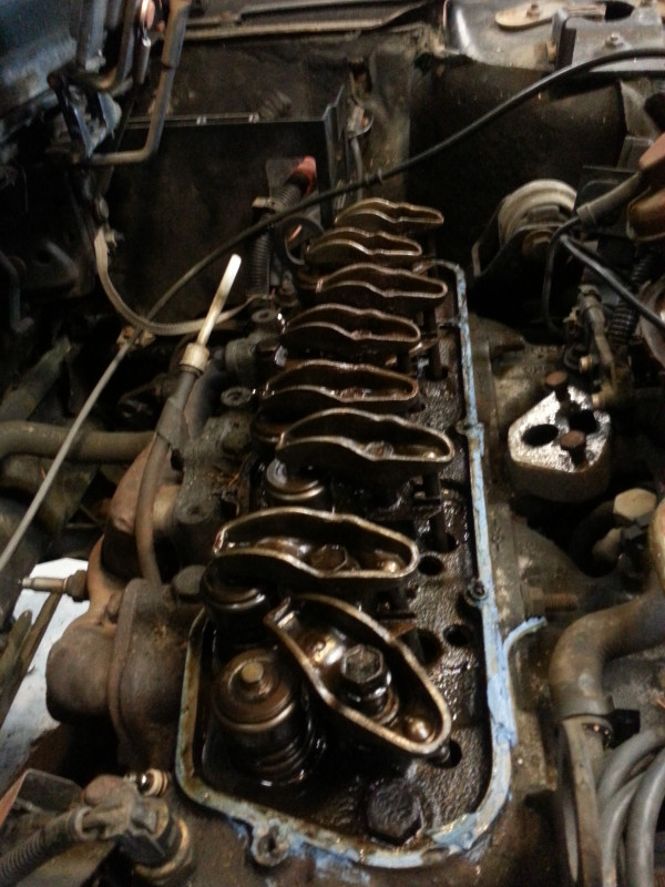
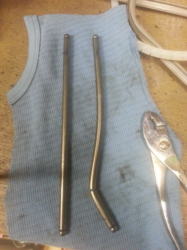
What I found under the valve cover (left), and the broken pushrod (right).

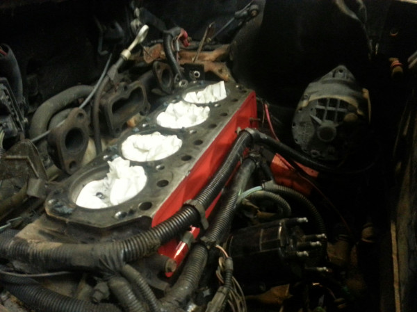
At this point I was pretty enthused, I finally had an excuse to rebuild a sizable part of an engine.  So I pulled off the cylinder head, and tore it down until it was bare. Then I packed it all up and cleaned everything in a chemical wash basin after hours at work. I honed all the valves, and replaced the one that had jammed. I took some time while everything was apart to paint the pushrod and valve covers fire-engine red with some spray on engine enamel.

804090268

By the time I got the head reattached, my dodge blew and intake manifold gasket, and since nothing can ever be easy on a Chrysler product, I spent the rest of what was left that summer dealing with repairs on my truck. Ultimately, I ended up getting it running well enough to trade in toward my Forester with 40,000 more miles and ten times the reliability. And so now I eagerly await this coming summer when I can finish reassembling the engine and test out the Fiero.

Field Day 2013

This Summer, I had quite a bit of fun at Field Day 2013. I joined the Saginaw Valley Amateur Radio Association for their Field Day outing. Running a Kenwood TS-520S I recently picked up, along with the matching AT-230 tuner, I strung up a G5RV antenna in some nearby trees (with help form the club). It was the first time since I got on the air with the rig since I bought it.

Field Day 2013

From 1800UTC to 0200UTC I made a total of 12 contacts, ranging in from New England to Texas, and everywhere in between. It was a great time and really got my feet wet in the world of HF.

Time (UTC) Station Frequency (MHz) Mode Location
19:11 W4RAT 14.300 USB Virginia
19:35 N0FUK 14.275 USB Iowa
19:37 W1CUM 14.320 USB New Hampshire
21:04 K4OO 14.290 USB North Carolina
23:30 K4PMH 14.290 USB Virginia
23:35 WB4ZPI 14.343 USB Alabama
23:38 WE1CT 14.275 USB ——
23:44 W5WB 14.320 USB Texas
23:50 W5CCW 14.330 USB ——
00:39 AC8IE 14.309 USB Ohio
00:58 WC9AR 14.231 USB Indiana
01:23 N5TT 14.300 USB Texas

A 2-Stage Headphone Amp Using the TPA6120 and OPA134

I recently had to design a 2 active stage amplifier for a class. So, I turned to my favorite OpAmp, the TPA6120 (check out my older post for more info about this IC). The datasheet for this IC recommends using it in conjunction with the Burr Brown OPA134, another fantastic little OpAmp. Though not quite as fast as the mighty TPA6120, the OPA134 has a very respectable 8 MHz bandwidth and 0.00008% THD.

BTW: Given the difficult to mount SO-20 PowerPad package TI uses for the TPA6120, I now offer a breakout board at AstrusLabs.com.

 For this project, I took what I had leaned from my implementation of the C-Moy amplifier design, and designed a new circuit with the same four stages as before:

Figure 1: Left Channel Amplifier Circuit

(A) Input Stage


A potentiometer (or pot for short), R1, is used as a voltage divider to control the volume on the input side. The pot is chosen based on resistance and number of turns. The resistance of the pot should be significantly higher than the output impedance of the source (i.e. the MP3 player plugged into the amp).  The number of turns determines the resolution, a 10 turn 1kΩ will allow for more sensitive fine tuning than a single turn 1kΩ pot. I used a pair of 50kΩ single turn pots this time which seem to work well (I usually just try whatever I have on hand for this part and see what works).

(B) Filter Stage


The filter stage serves to protect the amp and headphones from a DC biased input, and prevents high frequency noise from making it’s way into the circuit. Unlike the stock CMoy design’s passive low-pass filter, this circuit uses the OPA134 (IC1) in an inverting active band-pass filter configuration; calibrated to filter out signals below 10 Hz, as well as signals above 60 kHz. The range of human hearing is about 20 Hz to 20 kHz, so this easily encompasses that with some extra padding.

To define the two cutoff frequencies (fc), the below equation is used twice:

rc_filter

Once using R2.1 and C1, for the low frequency cutoff, and once using R2.2 and C2 for the high frequency cutoff. I chose to use 1kΩ resistors for both and derived the capacitor values from there. It is notable to mention that using two different resistors will result in an application other than unity gain at this stage, so it’s best to choose the resistors first.

(C) Amplifier Stage


The amplifier stage is simply an inverting OpAmp configuration using the TPA6120 (IC2). Owing to the TPA6120’s relatively low input impedance,   developing an unwanted DC bias across the input pins has been known to be a common issue when implementing this IC. To address this, normally one would attempt to balance the path to ground resistance from each input. In this case a third resistor, R3.3, can be used to balance the path-to-ground resistance on the input pins. Because the OPA134 is in the path, calculation of this value is more difficult. To determine the correct value for R3.3, I installed a 50kΩ potentiometer, and adjusted it while monitoring the circuit with an oscilloscope. I should mention that simply grounding the non-inverting pin only results in 60mV offset, so the consequences aren’t quite as drastic as in the previous amplifier.

It may be tempting to address the issue of DC-bias with a decoupling capacitor on the front end; however, the TPA6120 datasheet specifically recommends against this solution, since it may produce undesired oscillations on the output signal. The datasheet also offers a lot of other good design considerations, and I do recommend reading it over before modifying or designing your own amplifier.

 (D) The Driven Load


This portion of the circuit represents the impedance of the speakers being driven. In my case this would be the impedance of one side of a pair of AKG K-240 Studio headphones, or 55Ω.

 Other Considerations


The TPA6120 is a very finicky IC, and requires very clean power. It is necessary to use decoupling capacitors (preferably low ESR, though I’ve had good results with electrolytics too) .


Creative Commons License A 2-Stage Headphone Amp Using the TPA6120 and OPA134 Blog Post by Cheesed-Off.com is licensed under a Creative Commons Attribution-ShareAlike 3.0 Unported License.

Designing a Headphone Amp Around the TPA6120

I really wished this information was more readily available when I built my amplifier circuit, which is the reason I’m writing this. After purchasing a pair of AKG K-240 Studio Headphones, I decided I wanted a headphone amp to help drive them, and decided to build one, more or less, for the educational value. Having built electronics kits in the past, I really didn’t want to just assemble a pre-existing kit. After reading about various OpAmps, I settled on the TPA6120. This IC operates between 5V and 15V, a fine range to power with 9V batteries. It also has a very fast slew rate 1300V/μs, low noise, and a low THD rating.

Update: Given the difficult to mount SO-20 PowerPad package TI uses for the TPA6120, I now offer a breakout board at AstrusLabs.com.

I should mention before continuing, this information applies to headphone amp design, and I cannot comment on it’s compatibility with other applications (such as guitar or microphone preamps). If you’re interested in driving something other than headphones, I suggest you look into the specific design considerations for your application.

 As a starting point, I referenced the four stage C-Moy amplifier design:

Figure 1: Left Channel Amplifier Circuit

(A) Input Stage


A potentiometer (or pot for short), R1, is used as a voltage divider to control the volume on the input side. The pot is chosen based on resistance and number of turns. The resistance of the pot should be significantly higher than the output impedance of the source (i.e. the MP3 player plugged into the amp).  The number of turns determines the resolution, a 10 turn 1kΩ will allow for more sensitive fine tuning than a single turn 1kΩ pot.

I used a pair of 2.2kΩ single turn trim-pots I pulled from an old Behringer Amp; which seem to work well for me, but may or may not fit your needs.

(B) Filter Stage


The filter stage serves to protect the amp and headphones from a DC biased input. The job of the capacitor (C1) is to block DC, and the job of the resistor (R2) is to set a predictable high pass cutoff frequency. Together these two components function as a highpass filter. The cutoff frequency should be below 20Hz (the lower extent of human hearing), and is found using the equation:

rc_filter

where fc is the cutoff frequency, R is the resistance of R2 in Ohms, and C is the capacitance of C1 on Farads.

For reasons I will explain later, I chose values of 175Ω and 220μF for R2 and C1, resulting in a cutoff frequency of  approximately 7Hz, well below the 20Hz limit.

(C) Amplifier Stage


The amplifier stage is simply a non-inverting OpAmp configuration. There is a lot of information available elsewhere that would do a far better job than I could, explaining how this amplifier configuration works. The important thing here is the gain equation:

gain

This determines how much larger (or smaller) the output is compared to the input. Since the TPA6120 datasheet recommends a value of 1kΩ for the feedback resistor: I chose resistance values of 240Ω and 1kΩ for R3.1 and R3.2, respectively;  resulting in a gain of approximately 5.

Since the TPA6120 has a relatively low input impedance for an OpAmp, balancing the apparent impedance at the input is crucial to prevent a DC bias from forming at the output. This simply means that the resistance between each input pin and ground should be close to the same value. For this amplifier circuit, it means the resistances of R2, R3.1, and R3.2 are all related by the following equation:

resistance

This relationship (along with the availability of parts in my collection) is why a resistance of 175Ω was chosen for the filter stage; the capacitance was chosen based on what I had on hand.

It may be tempting to address this issue by adding a decoupling capacitor on the front end; however, the TPA6120 datasheet specifically recommends against this solution, since it may produce undesired oscillations on the output signal. The datasheet also offers a lot of other good design considerations, and I do recommend reading it over before modifying or designing your own amplifier.

 (D) The Driven Load


This portion of the circuit represents the impedance of the speakers being driven. In my case this would be the impedance of one side of a pair of AKG K-240 Studio headphones, or 55Ω.

 Other Considerations


While batteries do supply very clean power, I still found it necessary to use decoupling capacitors on the power pins to eliminate noise. As an added precaution I also wound the battery clip leads into twisted pairs to further cut down on RF interference.


Creative Commons License
Designing a Headphone Amp Around the TPA6120A2 Blog Post by Cheesed-Off.com is licensed under a Creative Commons Attribution-ShareAlike 3.0 Unported License.

Off To The Races!

Back in March, I volunteered for three events: the Keweenaw Winter TSD Rally, The Copper Dog 150, and the Great Bear Chase.

The TSD Rally was a blast, i got to ride all over the the Copper Country with Jack Swift N8WAV, one of the most interesting people I’ve ever met. Leaving Houghton late in the morning we sped across the western UP setting up and running check points throughout the course. Being a TSD rally the racers weren’t driving full speed, so we could take shortcuts from  checkpoint to checkpoint with a little time to spare and set them up before the racers would arrive. In Jack’s own words “the job was a lot of hurry up and wait.” Although, when the racers would cross the check points it was a mad dash to to take down times and pass out tickets as each car crossed; and alot of them were very close together. After about five hours or so we were back in Houghton enjoying dinner at the North Shore Grill and passing out awards.

Two weeks later I volunteered with net control at the Copper Dog 150, this was by far the most fun I have had in HAM radio yet, I got to work with Bill KD8JAM and Howard KD8ABP, who were very helpful in teaching me the ins and outs of acting as a net control operator, and a lot of really useful general HAM info as well.

The Copper Dog 150 is a three day dog sled race. On day one the sleds left from downtown Calumet and raced up to Eagle Harbor. On day two, they raced up to Copper Harbor; and on day three back to Calumet. Day one I was mainly observing, although I did get to make a run out to a checkpoint in Laurium, where reception was low, to assist with radio communication. As day one drew to a close and the sleds made their way into Eagle Harbor, one team stalled out 2 miles from town. This kept a small handful of volunteers in the field (including a good friend of mine, KD8OXB) up until a little after 3am. On day two I actually got to work net control all day with KD8JAM. Day three I helped track the race official car locations. Both day two and day three ran smoothly with a couple small hiccups here and there.  In the end it was bib #23, JR Anderson, and his team that took First place, a first for him and his team. Congrats.

A week after that  I volunteered as a field radio operator in the Great Bear Chase, a cross country skiing race. This was the most uneventful of the three races I helped with that month. I mainly worked at checkpoint as a HAM operator and providing refreshments to the racers, nothing noteworthy happened related to radio operations.

All in all, Volunteering was pretty fun, and something I look forward to continue in the future.

A First Taste of DXing

Over the past couple week I’ve been reading a lot of all over the web about all the fun things to do in HAM Radio: DXing, satellites communications, antenna construction, moon bounce, etc. One thing I latched onto was Amsat, I spent a lot of time on their website. After downloading some satellite tracking software I headed up to the Ham Shack with the anticipation of picking up a beacon from something overhead.  To my dismay the only VHF/UHF radio that was capable had a misaligned antenna, and I didn’t end up hearing anything from space. But I did pick up some DXers on 20-meters, while playing with HF transceiver. To my amazement I was able to pick up signals from Tennessee, Florida, and Arizona. Being only a Technician Class Operator I could not legally attempt to make contact. But it did light a fire under me to get studying for the next HAM Exam.

The Carnival and The Companion Cube

It’s been a week, since I got on the air. I’ve stumbled through a couple QSOs during the week, and there’s still a lot I have to learn. I got my Alinco rig set up and running. Although, I am a little worried about the audio equipment in my apartment and neighboring apartments, since when I powered it up for the first time, I left my desktop speakers powered on and they screeched loudly with noise when I tried to transmit. I’ve since moved my antenna, however there is a hiss when I transmit. I’m not too worried about damaging anything since I moved the antenna, but I hope I’m not annoying anyone around me.

Last night was the first night of Winter Carnival here at Michigan Tech. While my friends and I were busy away building an 8 ft Companion Cube snow sculpture, a number of us were carrying our handy talkies. And with three feet to go in the mold, a friend of mine stops the operation announcing that he cannot find his radio. I pulled out mine and sent out a test message over a local repeater he was last tuned into. And we mix of relief and concern, when a slight sound could be heard coming from beneath the snow. I kept transmitting for a little while to help out, and after some digging, the radio was recovered.

An Amazing First Week

Last weekend I took the HAM test and got Technician Class License, almost on a spur-of-the-moment. The night before test I heard about the exam and decided I’d give it a go, and crammed for it in a few hours. I didn’t pass the first test I took, but I did make Technician on my second try.

That Thursday, I popped in the Michigan Tech HAM-Shack for a weekly meeting of the Husky Amateur Radio Club (HARC),  and joined the club.

Finally on Friday and I was checking the FFC call-sign directory compulsively all day until just before the end of the day when it finally appeared; I was exuberant. I couldn’t wait for work to get. When I did get out, I headed straight up the HAM-Shack and checked out a Handy-Talkie. I started monitoring the Eighty-Eight (146.88 MHz), and finally around 11PM, I made contact with a fellow named Terry, but who’s call-sign I fail to remember. He was nice enough to give me (and two friends that were with me at the time), a heads up on a swap meet that was planned to take place the next morning a little over two hours away. Needless to say I went straight to an ATM and then straight to bed.

The next morning I woke up at 5:45 AM and was on the road by 6:30 AM. By 9:15 AM we were at the Swap and I was busy negotiating a deal on an Alinco DR-600T Twin Band Transceiver. And just like that, I License, Letters, and Radio all in a little under a week.

Interestingly enough, I ran into a lot of interesting folk at the Swap: A HARC Alum, A couple of the Testers from my examination, and even Terry. All in all, it’s been a pretty cool week.